ddm
Basic Modelling
Content
First of all. The Help tool (you can also press F1) in Rhino is very well done and very complete. Don’t hesitate to use it.

Rhino 6 Interface
Modeling in 3‑D is the process of creating a mathematical representation of an object’s surfaces. The resulting model is displayed on your screen as a two-dimensional image. Rhino provides tools for creating, displaying, and manipulating these surfaces.
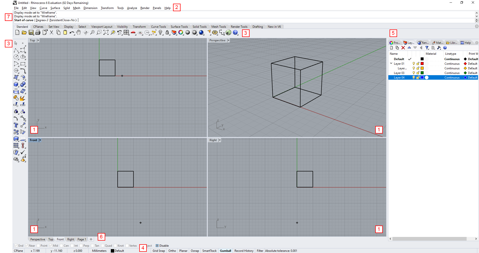
- Viewport (Display different views within the graphics area)
- Menu Bar (Access commands, options and document properties (e.g. model units))
- Tool Bar (Basic Modelling tools)
- Status Bar (Displays options, toggles, coordinates)
- Panels (Displays specific options such as layers, object properties, cameras etc.)
- Add Layout (Add set views or layouts to fast navigate btw. viewports)
- Command Prompt (List of commands and prompts)
Viewports

You can reset the viewport by clicking the “Viewport Toggle” icon
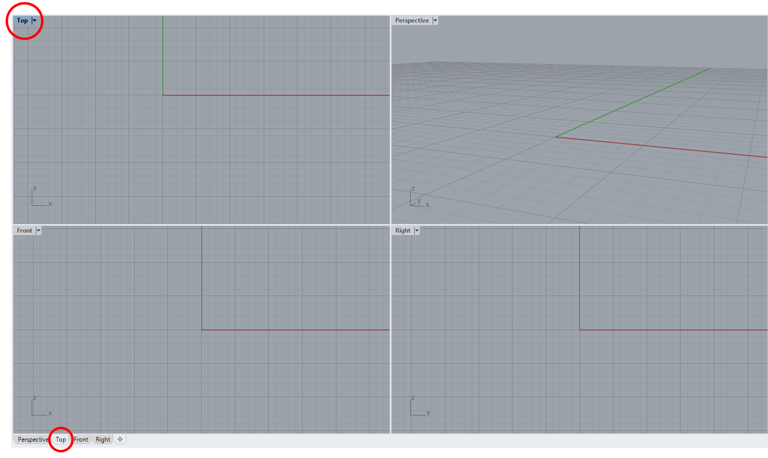
Viewports are windows in the graphics area that display views of your model. They can be docked or floating. You can customize the viewports and their positions to suit your preferences. The size and position of viewports is adjustable; they can be any rectangular size and shape. Each viewport has its own construction plane and grid that the cursor normally moves on and a projection mode. To toggle between a small viewport and one that fills the graphics area, double-click the viewport title.
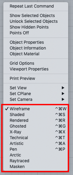
Rightclick on the viewport title to:
- Change Display Mode
- Set View
- Set Camera
The Standard layout in Rhino is four viewports. Doubleclick on the viewport title, and this >one will become the main panel. Doubleclick again and it will revert to a 4-panel-view. >Viewport tabs can be activated to facilitate navigation through panels. You can also >navigate between the viewports at the bottom left.
Navigation

There are several types of navigation tools, which you can find in the toolbar above
Working in 3D on a computer requires visualizing 3D objects drawn on a 2D medium - the computer screen. Rhino provides tools to help do this. Rhino’s easy view navigation helps you visualize your model. You can look at you model from any direction, look at the whole model, or look into the details. You can also change your view in the middle of performing a command to see precisely where you want to select an object or pick a point.
Mouse Navigation

- Pan - In viewports with parallel projections (for example: Top, Front, and Right), drag with the right mouse button. In perspective viewports, hold the Shift key, and drag with the right mouse button.
- RotateView (Orbit) - In perspective viewports, drag with the right mouse button.
- Zoom - Hold the Ctrl key, and drag up and down with the right mouse button, or use the mouse wheel.

- Zoom Extents - Zooms the view to show all objects currently visible.
- Zoom Selected - Zooms the view to show all selected objects.
- Undo View - The UndoView command reverses recent view changes.
- Undo a command - On the Edit menu, click Undo. Or press the “Ctrl + Z” keys.
- Hide / Show - The Hide command conceals selected objects from view. To show again: Rightclick and “Show Objects”
- Fly out toolbar - Tools with a little triangle have a flyout toolbar options to complete similar tasks in different ways.
Display Modes

You can either change the display mode by toggling the icon above or rightclick the >viewport title.
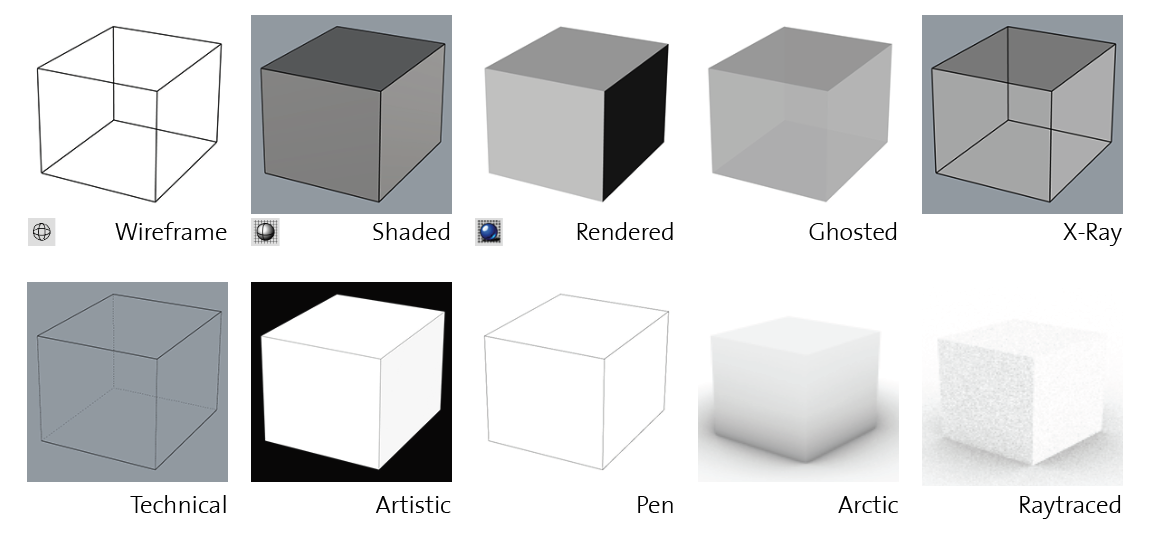
You can view your model in a variety of wireframe, shaded and rendered methods that depend >on your needs.
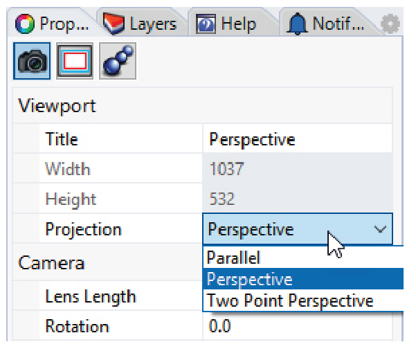
The perspective viewport projection can be parallel, three-point perspective, or two-point perspective. The viewport projection is set in Viewport Properties. When no object is selected, the Properties panel shows viewport properties.
Units

You can access the units properties through the File Menu (File > Properties > Units)
As soon as Rhino is launched, you are prompted to choose the units of the model you will be working in. For general landscape modelling we recommend to choose “Meters”, for CNC Milling the unti of choice should be “Millimeters”.
Basic Modeling

Rhino is a command-driven program. In other words, all actions are activated by named commands.
Toolbars contain graphical icons for initiating commands. Many toolbar icons have a second command that can be accessed by right-clicking the icon. The tooltip that appears when you hover over the icon tells you what the left and right mouse button would lead to.
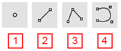
- Point(s) - Point objects mark a single point in 3‑D space. They are the simplest objects in Rhino.
- Line - The Line command draws one line segment.
- Polyline - The Polyline command draws a series of lines.
- Curve - The Curve command draws a curve from control points.
Tips: You can just start typing, there is no need to press on the command prompt. To confirm the command you can press spacebar or enter or right-click You can also repeat the last command by press either spacebar, enter or rightclick (on viewport). To Cancel stuff, just press ESC

Many commands provide secondary options to allow additional options. By clicking on the (Vertical=No) option it will change to “YES”, allowing you to move your objects only in Z-Axis. These secondary options are also often accessible through the flying toolbar.
Status Bar


Object Snap (OSNAP)

- Osnap The object snaps constrain the marker to an exact location on an object such as the end of a line or the center of a circle.
- End Snap to the end of a curve, line etc.
- Near Snap onto a curve near the cursor location.
- Point Snap to a point object or a control point of a line or curve.
- Mid Snap to the midpoint of a curve, line, polyline segment etc.
- Cen Snap to the center of a circle, box etc.
- Int Snap to the intersection or projected intesection of curves, lines, edges etc.
- Perp Snap perpendicular to a curve.
- Tan Snap tangent to a curve.
- Quad Snap to the point on a curve that is at the max. x or y point relative to the current construction plan.
- Knot Snap to a knot on a curve or surface.
- Vertex Snap to a mesh vertex. Your only option to snap on a mesh object.
Other Options

- Grid Snap Forces the Marker to snap on grid intersections.
- Ortho Restricts cursor movements to the points at a specified angle from the last point created. The default angle is 90 degrees. You can temporarily turn this off by pressing Shift.
- Planar This helps you model objects in the same projected plane by forcing input to be on a plane normal to the last point you picked its imagined connection to your viewport position.
- SmartTrack SmartTrack™ is a system of temporary reference lines and points that is drawn in the Rhino viewport.
- Gumball The Gumball command displays the gumball widget on a selected object facilitating move, scale, and rotate transformations around the gumball origin.
- Record History Records history and updates history-aware objects. With history recording and update turned on, e.g. a lofted surface can be changed by editing the input curves.
- Project Osnap By default, 2D geometry is created on the active construction plane. The project constraint ignores object snaps and pushes all the geometry onto the active construction plane.
- Disable Osnap The DisableOsnap command manages the state of persistent object snaps to temporarily turn off persistent object snaps from the control.
Layers

You can access the Layer functions through the Edit Menu (Edit > Layers > Edit Layers) or >from the Tool Bar.
Setting up Layers
Layers are a way of grouping objects and applying certain characteristics to all objects that have that layer assignment. Layer states include a layer name, the color used to display the objects, and the visibility and the possibility to lock/unlock all the objects on a layer. Objects are always created on the current layer indicated by the little tick. Only one layer can be active at a time. Objects may also be copied or moved to other layers later. Objects on layers that are off are not visible in the model. Objects on locked layers cannot be selected but can be snapped to.
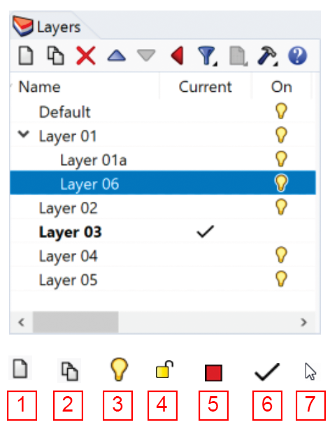
- New Layer
- New Sublayer
- Change the on/off state
- Change the locked/unlocked state
- Change the layer color
- Set the current layer
Doubleclick to change the Name
Rightclick to:
-Select Objects on Layer -Change/Copy selected object to layer
Layouts

Use a layout to arrange the model for the printer. (View > Layout > New Layout)
Viewport to layout To add a new layout to your rhino file either do:
- Viewport Tab: Rightclick on “+” and “New Layout”
- Via Command prompt: Type: “Layout”
- Via Menu: View > Layout > New Layout
Properties By selecting “New Layout” a window pops up to define certain layout properties. These can be changed afterwards again.
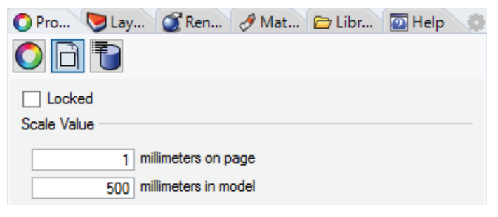
Set scale
- Click on the Frame of your View (in the Layout)
- Go to “Properties” then click on “Detail”
- Set Scale